In industrial automation, Programmable Logic Controllers (PLCs) play a crucial role in controlling machinery, managing systems, and improving productivity. One of the most widely used programming methods for PLCs is the ladder logic diagram, a visual tool that represents how the logic flows through the control system.
This blog will guide you through the essentials of the logic diagram PLC, introduce you to PLC ladder programming, and help you understand how logical gates like AND and NAND are implemented using ladder logic.
What Is a Logic Diagram in PLC?
A logic diagram PLC is a schematic representation of the control logic that a PLC executes. These diagrams are essential for designing and understanding the behavior of automated systems.
The most common form is the ladder logic diagram, which resembles a ladder with vertical rails and horizontal rungs—each rung representing a logical operation.
What Is Ladder Logic?
Ladder logic (also called ladder programming) is the traditional programming language for PLCs. It mimics the look and structure of electrical relay logic diagrams used before digital PLCs became standard.
In PLC ladder programming, the logic is built with contact symbols (representing inputs or conditions) and coil symbols (representing outputs or actions). These elements are organized into PLC ladder diagrams that run from left to right.
Key Components of Ladder Logic:
- Normally Open (NO) Contact – Logic condition is true when input is ON
- Normally Closed (NC) Contact – Logic condition is true when input is OFF
- Coil (Output) – Represents the output device or action
- Branches – Used to create parallel operations (OR conditions)
Why Use PLC Programming Ladder Logic?
PLC programming ladder logic is preferred for several reasons:
- Easy to Understand – Especially for those with an electrical background
- Graphical Format – Makes troubleshooting and logic tracing simpler
- Widely Supported – Almost every major PLC manufacturer supports ladder logic
- Reliable – Time-tested in real-time industrial environments
Basic PLC Ladder Diagram Example
Let’s look at a basic PLC ladder diagram that turns ON a motor when two input conditions (Start and Safety Switch) are true.
|—-[ Start ]—-[ Safety ]—-( Motor )—-|
This is equivalent to an AND Gate Ladder Diagram where the motor turns on only when both conditions are true.
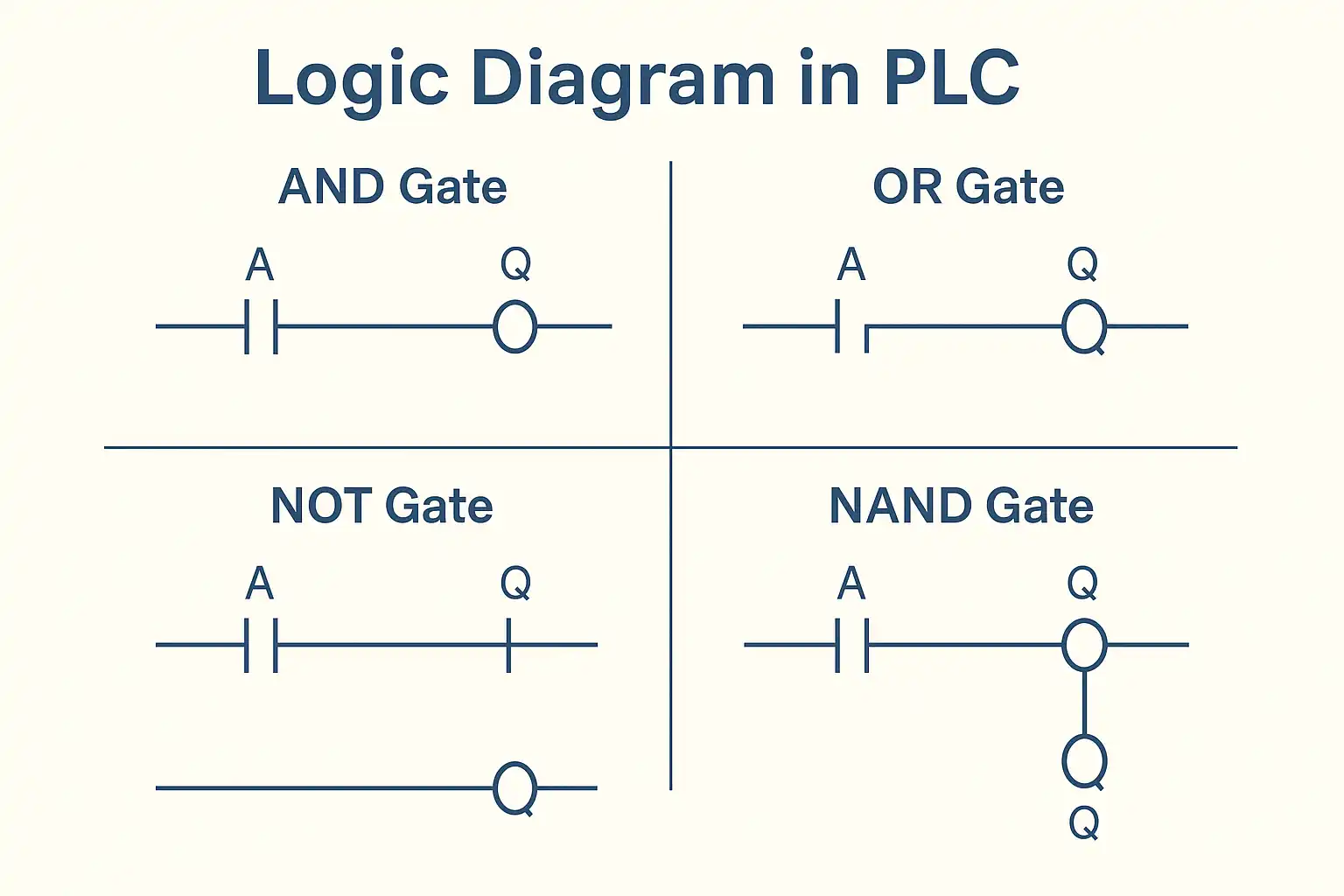
PLC Diagram for Logic Gates
Understanding ladder diagram for logic gates is key to mastering PLC logic. Let’s break down a few examples:
✅ AND Gate Ladder Diagram
Logic: Output is ON only if Input A and Input B are both ON.
|—-[ A ]—-[ B ]—-( Q )—-|
✅ OR Gate Ladder Diagram
Logic: Output is ON if either Input A or Input B is ON.
|—-[ A ]———–( Q )—-|
|—-[ B ]——————–|
✅ NOT Gate Ladder Diagram
Logic: Output is ON when Input A is OFF.
|—-[/A ]————( Q )—-|
✅ NAND Gate Ladder Diagram
Logic: Output is OFF only if both A and B are ON; otherwise, it’s ON.
|—-[ A ]—-[ B ]—-[/]—-( Q )—-|
Ladder Logic Programming: Real-World Application
Let’s say we want to design a control system where:
- A conveyor runs when a sensor detects an object AND the emergency stop is not pressed.
Ladder PLC Program:
|—-[ Sensor ]—-[/ E-Stop ]—-( Conveyor )—-|
This real-world scenario uses ladder logic programming to ensure safety and operational control.
Basic PLC Diagram Symbols
| Symbol | Meaning |
| [ ] | Normally Open Contact (Condition ON) |
| [/] | Normally Closed Contact (Condition OFF) |
| ( ) | Output Coil (Action or Output) |
| ` |
These basic symbols form the backbone of any basic PLC diagram.
Where Is Ladder Logic Used?
PLC ladder logic is commonly used in:
- Manufacturing lines
- Packaging machines
- Water treatment plants
- HVAC systems
- Elevator systems
- Safety and emergency control circuits
- Mechatronics systems
It’s an essential tool for automation engineers and electricians alike.
FAQs on PLC Ladder Logic and Diagrams
Q1: What is the difference between a logic diagram and a ladder diagram?
A logic diagram shows the theoretical flow of logic operations, while a ladder diagram shows how those logic operations are implemented in a PLC using ladder symbols.
Q2: What is the function of a PLC ladder diagram?
It visually represents the logic program in a format that mimics electrical relay control systems, making it easy to design and debug automation systems.
Q3: How do I create an AND gate in ladder programming?
Use two normally open contacts in series to represent an AND condition.
Q4: Is ladder logic easy to learn?
Yes. Its visual format is especially intuitive for those familiar with electrical wiring and logic circuits.
Q5: Can PLCs use languages other than ladder logic?
Yes. PLCs also support Function Block Diagram (FBD), Structured Text (ST), Instruction List (IL), and Sequential Function Chart (SFC), but ladder logic remains the most common.
Conclusion
Mastering the logic diagram PLC and becoming comfortable with PLC ladder logic is crucial for anyone involved in automation or industrial control systems. Whether you’re designing a simple ON/OFF control or a complex logic circuit involving AND, OR, and NAND gates, ladder logic gives you the tools to make it happen—visually, efficiently, and reliably.
Start with basic PLC ladder diagrams, explore real-world use cases, and you’ll quickly realize how powerful and versatile ladder logic programming really is.
Related Blogs
- PLC Working Principle: How PLC Works
- Top Advantages of PLC
- What is PLC Panel
- Modular PLC: Flexible Approach to Industrial Automation
- What Micro Size PLC Can Handle
- Understanding PLC Basics: Beginner Guide to PLC Basics
- PLC Programming Languages: Complete Guide to PLC Language Types
- AB PLC: The Power Behind Industrial Automation
- History of Programmable Logic Controller (PLC)
- Understanding PLC Input and Output
- PLC Applications: How PLC Powers Modern Industry
- Top PLC Manufacturers
- Understanding Different Types Of PLC