In the world of industrial automation, nothing happens without PLC input and output. These are the essential channels that allow a Programmable Logic Controller (PLC) to interact with real-world machines and processes.
Whether you’re an automation beginner or a technician refining your skills, understanding how PLC input and output works—and knowing the types involved—is a critical step in mastering control systems.
What Are Inputs and Outputs in PLC?
Inputs are the signals a PLC receives from the outside world. These can come from:
- Sensors
- Switches
- Pushbuttons
- Proximity detectors
- Temperature or pressure transmitters
Outputs are the actions the PLC controls in the real world. These could activate:
- Motors
- Solenoids
- Alarms
- Valves
- Lights or displays
Think of inputs as “what’s happening” and outputs as “what to do about it.”
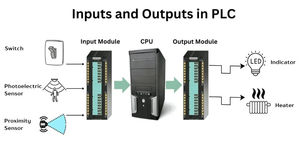
How PLC Input and Output Work Together
The PLC input and output system forms a loop:
- Input Devices send signals to the PLC (e.g., a button is pressed).
- The PLC processes those signals using the programmed logic.
- Based on that logic, the PLC activates or deactivates output devices (e.g., a motor starts running).
This process happens in milliseconds—allowing real-time control and decision-making in industrial systems.
PLC Input Output List: Common Devices
Here’s a basic PLC input output list to help you visualize common I/O devices used in automation:
| Type | Device Example | Signal Type |
| Input | Push Button | Digital (On/Off) |
| Input | Limit Switch | Digital |
| Input | Temperature Sensor (RTD) | Analog (Variable) |
| Input | Proximity Sensor | Digital |
| Output | Relay | Digital |
| Output | Motor Starter | Digital |
| Output | Analog Valve Actuator | Analog (0-10V or 4-20mA) |
| Output | Alarm Buzzer or Indicator | Digital |
These inputs and outputs are wired to the PLC’s I/O modules, and the type of signal—digital or analog—determines how the PLC processes them.
Digital vs. Analog Inputs and Outputs
Digital Inputs/Outputs
- Binary signals: only two states (ON/OFF or 1/0)
- Used for devices like switches, relays, and contact sensors
Analog Inputs/Outputs
- Variable signals: such as voltage or current
- Used for devices like temperature sensors or flow meters
- Requires analog-to-digital conversion for PLCs to interpret
Understanding this difference is crucial for choosing the right module and designing effective logic.
Types of PLC I/O Modules
Modern PLCs are modular, meaning you can mix and match input and output modules based on your needs:
- Digital Input Modules – Receive ON/OFF signals
- Digital Output Modules – Send ON/OFF signals
- Analog Input Modules – Measure variable data (voltage/current)
- Analog Output Modules – Control variable outputs (speed, temperature, etc.)
- Specialty Modules – For high-speed counters, motion control, communication, etc.
Each module is connected to your PLC’s CPU and is programmed via PLC software such as RSLogix, TIA Portal, or GX Works.
Real-World Example: PLC Inputs and Outputs in a Conveyor System
Let’s look at a practical setup:
Inputs
- Start Button
- Stop Button
- Proximity Sensor (to detect object presence)
- Emergency Stop Switch
Outputs
- Conveyor Motor (Start/Stop)
- Indicator Light (Conveyor ON status)
- Alarm Buzzer (if E-Stop is pressed)
The PLC input and output list for this system will be clearly labeled in the control panel, making troubleshooting and expansion easier.
Best Practices for PLC I/O Design
- Label everything: Use clear tags and physical labels for each I/O.
- Use signal conditioners: For analog sensors to reduce noise.
- Test each I/O point during commissioning.
- Keep wiring organized for easy maintenance.
- Allow expansion: Design with future I/O needs in mind.
Conclusion: Why Understanding PLC Input and Output Matters
The PLC input and output system is the core of any automated process. Whether you’re building a simple machine or a complex production line, knowing how to select, wire, and program I/O devices ensures reliable performance.
And with a solid PLC input output list, you can easily manage installations, troubleshoot issues, and scale up with confidence.
Mastering I/O basics gives you the foundation to move forward in automation—toward motion control, PID loops, and IoT integration.
FAQs: PLC Input and Output
Q1: What is the difference between input and output in PLC?
Inputs bring real-world signals to the PLC; outputs let the PLC control external devices.
Q2: What are common examples of PLC inputs?
Push buttons, limit switches, proximity sensors, and temperature sensors.
Q3: Can a PLC have both analog and digital inputs?
Yes, most PLCs support both, but you need the appropriate I/O modules.
Q4: What is the typical voltage for PLC inputs?
Usually 24V DC for industrial PLCs, but other options (like 120V AC) exist.
Q5: How do I make a PLC input output list?
List all sensors (inputs) and actuators (outputs) used in your system, along with signal types and PLC terminal numbers.
Related Blogs
PLC Working Principle: How PLC Works
Modular PLC: Flexible Approach to Industrial Automation
What Micro Size PLC Can Handle
Understanding PLC Basics: Beginner Guide to PLC Basics
PLC Programming Languages: Complete Guide to PLC Language Types
AB PLC: The Power Behind Industrial Automation
History of Programmable Logic Controller (PLC)
PLC Applications: How PLC Powers Modern Industry
Logic Diagram PLC: Understanding PLC Ladder Logic and Programming Basics