VFD Working Principle – Detailed Explanation
A Variable Frequency Drive (VFD) works on the principle of controlling the frequency and voltage of the electrical power supplied to an AC motor. The speed of an AC motor is directly proportional to the frequency of the power supply, so by changing the frequency, the VFD changes the motor’s speed.
To understand the vfd working principle clearly, let’s break down the process step-by-step.
VFD Working Principle – In a simple version
Imagine you have a ceiling fan at home. It runs at one fixed speed when you switch it on. Now imagine instead of just a normal on/off switch, you have a magical controller that lets you smoothly change the speed to exactly what you want — slow, medium, fast — without wasting electricity or making any jerks.
That magical controller, for big industrial motors, is called a Variable Frequency Drive (VFD).
The Problem Without a VFD
Motors are usually designed to run at one constant speed, decided by the frequency of the electricity supplied to them. If your country’s electricity runs at 50 Hz, that’s the speed your motor will try to match.
But what if you don’t always need full speed? Running a motor at full speed when you only need half power is like keeping your car accelerator pressed all the way down in a traffic jam — wasteful, noisy, and stressful for the engine.
1. The Relationship Between Frequency and Motor Speed
In an AC motor, speed is calculated using the formula:
Speed (RPM) = (120 × Frequency) / Number of Motor Poles
If the frequency is reduced, the motor spins slower. If the frequency is increased, the motor spins faster.
The VFD uses this relationship to precisely control motor speed.
2. The Core VFD drive working principle
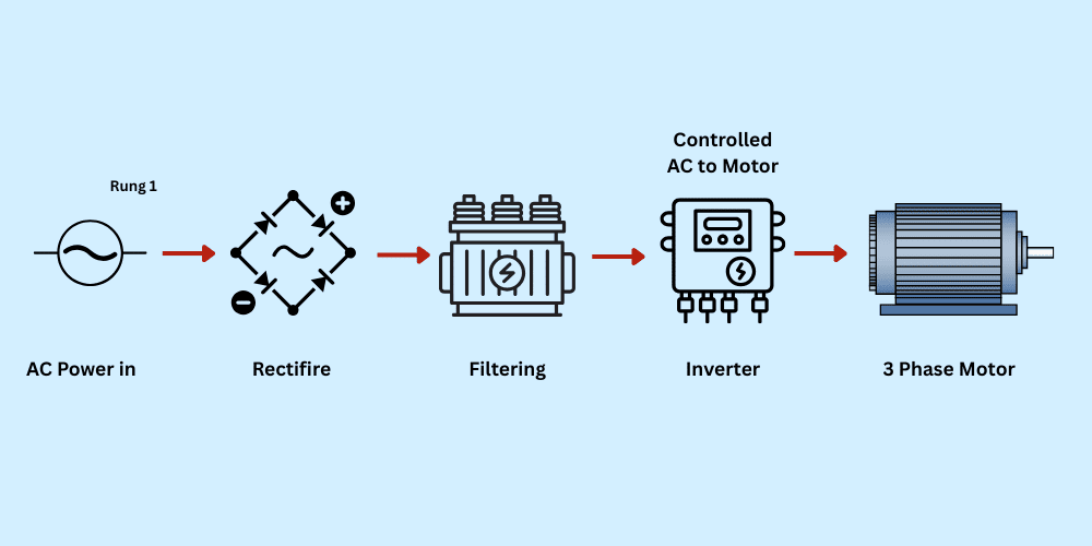
The VFD doesn’t directly change the incoming AC power’s frequency. Instead, it goes through a three-stage process:
Step 1 – Rectification (AC to DC Conversion)
The VFD receives fixed-frequency AC power (e.g., 50 Hz or 60 Hz) from the mains.
This AC power passes through a rectifier circuit, which converts it into DC power.
- This step is essential because frequency can’t be directly altered in AC form.
- Rectifiers often use diodes or controlled rectifiers for this conversion.
Step 2 – DC Link (Energy Storage and Smoothing)
After rectification, the DC voltage may have ripples. To make it smooth and stable, the VFD passes it through a filter section, usually made up of capacitors (and sometimes inductors).
- This stage acts as an energy reservoir.
- It ensures that the DC voltage is clean and consistent before being converted back to AC.
Step 3 – Inversion (DC to Controlled AC)
The smooth DC voltage is now fed into an inverter circuit.
- The inverter uses high-speed electronic switches such as IGBTs (Insulated Gate Bipolar Transistors) or MOSFETs.
- By switching these components on and off in a specific pattern, the inverter creates a new AC signal with the desired frequency and voltage.
- This output AC is then sent to the motor.
In a simple version, the variable frequency drive working principle – Step by Step
Step 1 – Taking the Power In
The VFD starts by taking the normal electricity from the wall — the kind that goes up and down (AC power).
Step 2 – Making it Steady
The VFD turns that up-and-down AC electricity into straight, smooth DC electricity. Think of it like taking choppy ocean waves and turning them into a calm, still lake. This is done using a part inside called a rectifier.
Step 3 – Storing and Preparing
The calm DC electricity is stored for a moment in a part called the DC link, like water in a tank. Here, any little ripples are removed so the power is perfectly smooth and ready.
Step 4 – Creating New Electricity
Now comes the magic. The VFD takes that smooth DC and, using tiny super-fast switches (IGBTs), turns it back into AC electricity — but this time, at exactly the frequency and voltage the motor needs.
It’s like refilling a river with water from your tank, but now you decide how fast the water flows.
Step 5 – Controlling the Motor Speed
By changing how quickly the AC “waves” come (the frequency), the VFD decides how fast the motor spins. If the waves come slower, the motor turns slowly. If they come faster, the motor speeds up. The VFD also changes the wave’s height (the voltage) so the motor gets just the right push — not too much, not too little.
3. How Speed is Controlled in Real-Time
The VFD constantly adjusts the frequency of the output AC to match the required motor speed.
- If lower speed is needed, it outputs a lower frequency.
- If higher speed is needed, it increases the frequency.
This method of keeping the Voltage-to-Frequency (V/F) ratio constant ensures the motor operates smoothly without losing efficiency or damaging itself.
4. Pulse Width Modulation (PWM) – The Key Technique
Most modern VFDs use Pulse Width Modulation to create the controlled AC output.
- The inverter generates pulses of voltage that switch rapidly between on and off states.
- By changing the width of these pulses, the VFD simulates a sine wave with the required frequency and voltage.
- The motor responds to this simulated sine wave just as it would to normal AC power, but now the frequency is exactly what the VFD wants it to be.
In a simple version
The VFD doesn’t actually create perfect smooth waves like the power company does. Instead, it sends thousands of tiny pulses of electricity every second. The width of these pulses changes to mimic a smooth wave. The motor can’t tell the difference — it just follows the rhythm and speed set by the VFD.
5. The Continuous Control Loop
Inside a VFD, sensors and microcontrollers constantly monitor the motor’s speed, load, and other parameters.
- If the load changes (e.g., a conveyor carrying more weight), the VFD adjusts the frequency and voltage instantly to maintain the desired speed and torque.
- This closed-loop feedback system ensures accurate and stable motor operation.
In a simple version
This whole process happens continuously, many times a second, so the motor’s speed is always exactly what’s needed. If the load changes — like a conveyor belt carrying more boxes — the VFD adjusts instantly, keeping things running smoothly without wasting power.
In Short
The VFD drive is working:
- Take fixed-frequency AC power.
- Convert it to DC using a rectifier.
- Smooth it using capacitors (DC link).
- Use an inverter to create new AC power at the desired frequency and voltage.
- Send this controlled AC to the motor to regulate its speed.
By following this process, the VFD achieves precise speed control, better efficiency, and smooth motor operation — all by mastering the relationship between frequency, voltage, and motor speed.